
Most 12 V and 24 V addressable LED strip projects do not fail at the LED. They fail where the driver IC is asked to live on a rail it was never specified for. A pixel driver is selected from a feature list, the strip is built around 24 V because the run is 8 metres long, and the first prototype comes back with dead pixels at the far end and a driver too hot to touch.
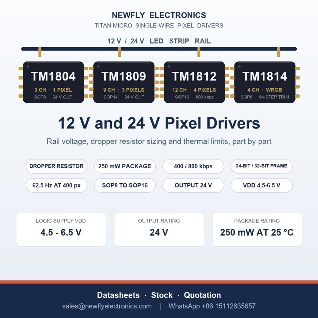
Titan Micro builds four single-wire pixel drivers that routinely end up on 12 V and 24 V strips: TM1804 (3 channels), TM1809 (9), TM1812 (12) and TM1814 (4, RGBW). They look interchangeable on a feature sheet. On a 24 V rail they are not, and the differences that decide the design are not the channel counts.
What follows is what the datasheets say about rail voltage, what the arithmetic does to the thermal budget, and how to choose between the four.
Why the rail voltage decides which driver you can use
A single-wire pixel driver is an open-drain current sink. LED anodes sit on the strip rail, cathodes go to the driver outputs, and the device pulls current to ground. That topology creates two separate voltage questions that buyers routinely merge into one:
- What can the output pin tolerate when it is off? With no current flowing, the pin sits at whatever the LED string pulls it to — effectively the rail. This is the output withstand rating, and it caps your rail voltage.
- What does the device need to operate? This is VDD, the logic supply, and it is a 5 V class figure on every part here. It is never 12 V or 24 V.
Get the first wrong and the parts die instantly. Get the second wrong and ignore the first and they work until a string goes open-circuit, at which point the output sits at full rail and the device fails in the field. Both failures arrive in the same RFQ inbox, usually worded as “your IC is faulty”.
What “24 V” actually means on these datasheets
Three of the four parts quote 24 V and it means the same thing on all of them: the output stage withstands 24 V. TM1814’s electrical table gives 24 V recommended and 32 V absolute maximum; TM1804 and TM1809 give 24 V. Some TM1809 feature lists circulate with 30 V instead — we publish the 24 V figure from the electrical table, because that is the table a design review gets signed against.
None of those figures is a VDD input range. Logic supply is specified at 4.5 / 5.0 / 6.5 V on TM1804, 5 V ±10 % on TM1809, and 4.5–6.5 V on TM1814. A buyer who reads “24 V” in a feature list and connects the strip rail to VDD has put 24 V on a 6.5 V maximum pin. That is the most expensive misreading in this family, and it is why supplier pages that copy feature bullets without the electrical table do real damage to their customers.
There is a second consequence. Because the output pin sees the rail when off, a 24 V rail leaves no headroom on a 24 V-rated output: inductive overshoot on a long strip lands directly on the pin. That is why 24 V installations are the ones that need the data-line series resistor and a clean supply.
Powering VDD from a 12 V or 24 V rail
Once VDD is understood as a 5 V class supply, the question is how to produce it. Three of the four parts are specified for a dropper resistor from the LED rail; TM1804 is not, and should not be treated as if it were.
| Part | VDD (logic supply) | How the datasheet expects VDD on a 12 V / 24 V strip |
|---|---|---|
| TM1804 | 4.5 / 5.0 / 6.5 V | Regulated 5 V rail. The 24 V figure is the output rating only; this part is not specified as resistor-fed. Derive 5 V separately. |
| TM1809 | 5 V ±10 % | 6–24 V operation is provided for through an external series resistor on VDD. |
| TM1812 | 5 V class, internal regulator | Internal 5 V regulator; the datasheet specifies a series resistor for 6–24 V supply. |
| TM1814 | 4.5–6.5 V, internal 5 V regulator | R = (VDC − 5.5 V) / 10 mA. 650 Ω on 12 V, 1.8 kΩ on 24 V. |
The TM1814 formula is the clearest statement of intent in the family. It sizes the resistor for 10 mA into VDD, not for LED current — because LED current never flows through VDD. It flows from the rail through the LEDs and the output stage to ground. VDD powers logic only, and TM1814 draws 2.8 mA typical; 10 mA is the headroom the datasheet wants for switching and regulator tolerance.
First-pass designs get this wrong in the opposite direction: the dropper is sized for total strip current, a power resistor the size of a fingernail gets fitted, and the driver browns out. Size it for logic current. On 12 V the resistor is trivial — 6.5 V across 650 Ω is 65 mW, a 0.25 W part. The 24 V case needs attention: 18.5 V across 1.8 kΩ is 185 mW, so specify 0.5 W minimum and do not bury it where it cannot breathe.
The dropper’s real cost on a long strip
Every pixel on the strip needs its own dropper, and on 24 V each burns roughly 185 mW continuously, whether the pixel is lit or not.
| Devices on the 24 V rail | Dissipated in dropper resistors | Practical reading |
|---|---|---|
| 100 | ≈18.5 W | Manageable, but it is heat inside the extrusion |
| 400 | ≈74 W | Now comparable to the LEDs themselves |
| 1000 | ≈185 W | Thermally unacceptable in a sealed profile |
Those are arithmetic from the datasheet design point, not a specification — but the conclusion is structural. Beyond a few dozen pixels, the droppers can out-dissipate the lighting function. Distributing 5 V alongside the 24 V rail and feeding VDD directly removes them entirely, at the cost of one conductor and one small supply. Short runs tolerate per-device droppers; façades and cove runs of several hundred pixels should plan 5 V distribution and choose the driver on data-path and thermal merit instead.
Thermal budget: the voltage the driver drops is the heat it makes
The output stage dissipates rail voltage minus LED string voltage, multiplied by the current it sinks. All four parts are rated 250 mW at 25 °C package dissipation. On a 12 V strip with a three-LED white section the drop is about 2.4 V. Run it for TM1814 at maximum setting:
| Case (TM1814, 4 channels) | Drop per channel | Package dissipation | Against the 250 mW rating |
|---|---|---|---|
| 12 V rail, 38 mA per channel | 2.4 V | ≈365 mW | Over. Do not ship this |
| 12 V rail, 20 mA per channel | 2.4 V | ≈192 mW | Holds, with little margin |
| 24 V rail, 7-LED section, 38 mA | 1.6 V | ≈243 mW | Just inside — derate for ambient |
The counter-intuitive result: a 24 V rail is often easier on the driver than 12 V, because a longer LED section consumes the voltage that would otherwise burn in the package. The 12 V strip is the one that needs a current setting below maximum. TM1814 is the only part here where that is a software decision — channel current is set in 64 steps between 6.5 mA and 38 mA via C1, with C2 as its exact inverse, validated at reset. TM1804, TM1809 and TM1812 are fixed at the datasheet rating, so on 12 V you control heat by choosing a longer LED section or a different part, not by trimming a register. The TM1814 vs TM1812 comparison works through the same arithmetic channel by channel.
Ambient closes the margin further. Package thermal resistance in this family starts around 79 °C/W; at 250 mW that is a junction rise of roughly 20 °C over ambient in a good layout and far more in a poor one. An outdoor install where a sealed profile sits well above 50 °C has to hold drop × current near 100–125 mW rather than the headline 250 mW.
The four drivers compared on a 12 V or 24 V rail
Supply-facing facts first — the columns a design review needs before anything else is discussed.
| Part | Channels / pixels per device | Package | Channel current | Output rating |
|---|---|---|---|---|
| TM1804 | 3 ch = 1 RGB pixel | SOP8, DIP8 offered | 40 mA min, 45 mA typ sink; 60 mA abs max | 24 V |
| TM1809 | 9 ch = 3 RGB pixels | SOP14, DIP14 | 50 mA typ, 80 mA max at 0.3 V | 24 V (electrical table) |
| TM1812 | 12 ch = 4 RGB pixels | SOP16, DIP16 | 45 mA class | 6–24 V supply via dropper; confirm output withstand against revision 02 for a 24 V design |
| TM1814 | 4 ch = 1 RGBW pixel | SOP8 | 6.5–38 mA in 64 steps via C1; 4 outputs paralleled = 152 mA | 24 V recommended, 32 V abs max |
The second table decides firmware and cascade planning, and it is where the family stops looking interchangeable.
| Part | Data word per device | Speed select | Datasheet cascade figure |
|---|---|---|---|
| TM1804 | 24 bit per pixel | SET pin: 400 kbps or 800 kbps | ≥512 px at 30 fps low speed, ≥1024 px high speed |
| TM1809 | 24 bit per pixel | SET pin: 400 kbps or 800 kbps | ≥540 px at 30 fps low speed, ≥1080 px high speed |
| TM1812 | 24 bit per pixel | No SET pin: 800 kbps only | ≥1080 px at 30 fps |
| TM1814 | 32 bit PWM word + C1/C2 pair and its inverse, 64 bit per device | No SET pin: 800 kHz external, 500 kHz internal mode | 400 px at 62.5 Hz, 800 px at 32.2 Hz, 1000 px at 25 Hz |
Read that last row carefully: TM1814 quotes refresh rate, while the other three quote frame rate at 30 fps. They are not the same measurement and should not be compared cell to cell. What matters for a purchase decision is this — a camera-safe refresh above 60 Hz holds to 400 devices on TM1814 and drops steeply beyond; if 30 fps is acceptable, the 24-bit parts cascade substantially further.
Firmware is not portable across the family
Three of the four consume 24 bits per pixel: eight bits per channel, three channels. Code written for TM1804 runs on TM1809 and TM1812 without a frame-format change, which is why one controller library covers all three. TM1814 does not join that group. It consumes a 32-bit PWM word for four channels, preceded by the C1 current command and its inverse — 64 bits per device on the wire — and the current command is forwarded by every device to the ones behind it, an overhead of roughly 80 µs per frame.
Two practical consequences when quoting a design. A 24-bit library driving a TM1814 string produces scrambled colours that look like a wiring fault, and teams lose a day to it before opening the datasheet. And a TM1812 string cannot run at 400 kbps: there is no SET pin, the part is 800 kbps only. A fixed 400 kbps controller rules out TM1812 and TM1814, leaving TM1804 or TM1809.
TM1814 also carries a hard boundary worth stating plainly. After 450–550 ms without data on DIN it enters internal-control mode and cycles a fixed ten-step white/red/green/blue pattern while still forwarding downstream, and there is no way to disable it. If the installation must go dark when the controller fails — common in architectural and stage work — this is the wrong part, and the 24-bit family with a hold-or-blank policy is the right one.
A five-question selection path
Answer these in order and the family narrows to one or two parts. The wider Titan Micro LED driver selection guide covers the segment-display families if the project is not a pixel strip at all.
- Is there a white channel? RGBW means TM1814 is the only option here. RGB means TM1814 is wrong — you would pay for a fourth channel you cannot use.
- What is the rail? 24 V rules out anything below a 24 V output rating, and makes the VDD dropper a wiring decision on long runs. 12 V leaves more thermal work to the package.
- What data rate does the controller already produce? 400 kbps only means TM1804 or TM1809. 800 kbps opens the whole family.
- How many pixels, and does anything need above 60 Hz? Past roughly 400 devices TM1814 loses refresh quickly; the 24-bit parts carry 1080 pixels at 30 fps.
- How much heat can the profile take? Sealed profile above 45 °C ambient: choose the part whose current you can trim, or lengthen the LED section until drop × current sits near half the package rating.
Where the demand is, and what each market asks for
India and Bangladesh — high-volume decorative and festival lighting, mostly 12 V for cost and because 12 V supplies are everywhere. The recurring request is a driver that survives maximum current on a short three-LED section, which is precisely the thermal case above.
Vietnam, Thailand, Malaysia, the Philippines — contract lighting and strip assemblies built for export to Europe and North America. These move to 24 V to hold brightness over 5–10 m runs and care about the VDD feeding method, because the strip is potted or sleeved and cannot shed dropper heat.
Middle East — façade and landscape work, high ambient, long outdoor runs. The derating argument above decides the purchase, and buyers are receptive to it: they have already replaced strips that failed in summer.
Europe and the United States — retrofit and architectural work where documentation is part of the purchase. These buyers want the datasheet revision number on the quotation, the output figure taken from the electrical table rather than the feature list, and a plain statement of what the part is not rated for.
Before you place the order
- Measure VDD on the strip, not the bench. Confirm the dropper lands between 4.5 V and 6.5 V at full white, not idle. Logic current rises with switching.
- Run maximum setting for twenty minutes and measure package temperature against your ambient assumption, not room temperature.
- Check the current command behaves. On TM1814, write C1 and its inverse C2 and confirm the part accepts or rejects the setting cleanly at reset.
- Confirm the datasheet revision you are designing against, in writing on the quotation. Our published figures come from TM1814 V1.1, TM1809 V1.5, TM1804 V2.2 and TM1812 revision 02.
Pixel drivers on a 12 V or 24 V rail: where it does not belong
Specification tables tell you what a part can do. Design failures come from what it cannot do. Before you commit a Pixel drivers on a 12 V or 24 V rail to a production board, check these cases — if any of them applies to your design, this is the wrong part and we will say so.
- your rail is above 24 V — a 36 V or 48 V bus — the output stage on TM1804, TM1809 and TM1814 withstands 24 V (32 V absolute maximum on TM1814). A higher rail puts the off-state output above its rating on every pixel. Reduce the bus to 24 V or use a part specified for the voltage.
- your controller is a 3.3 V MCU wired straight into DIN — VDD is a 5 V class supply and the input high level sits above a 3.3 V rail. Add a level shifter / buffer with a 100 Ω series resistor, or run the logic at 5 V. This is the most common mis-order on the family.
- you need digits, a keypad or a fixed segment display — these are pixel drivers with no decode, no display RAM and no key scan. Use TM1637, TM1650, TM1628 or TM1668 for segment LED panels, and TM1621B / TM1621C / TM1621D for LCD glass.
- the installation must go dark when the controller stops sending data — TM1814 enters internal-control mode after 450–550 ms without DIN and cycles a fixed ten-step white/red/green/blue pattern while still forwarding data downstream. It cannot be disabled. Use a 24-bit part and a hold-or-blank policy in the controller instead.
- you need more than 38 mA on four independent TM1814 channels — the four outputs can be paralleled to reach 152 mA, but then they are one channel, not four. Four independent channels above 38 mA is outside what this part can do.
- you are building a 24 V strip of several hundred pixels with a dropper on every device — each dropper burns about 185 mW. On 400 devices that is roughly 74 W inside the profile before a single LED lights. Distribute 5 V and feed VDD directly.
- your programme requires AEC-Q100 or a formal PPAP package — these are commercial-grade parts rated for −40 to +85 °C with no automotive qualification. We will decline the quotation rather than imply a grade the part does not carry.
Working with Newfly: the numbers
Buyers evaluating a supplier want the commercial parameters stated, not implied. Here is ours. Where a figure depends on your quantity, package or destination, we say so rather than publishing a number that will not hold.
| Item | What we commit to |
|---|---|
| Sample order | Sample and small-batch quantities are supported. Sample fee, freight terms and dispatch time are confirmed in writing with each quotation. |
| Minimum order | Flexible. We support partial-reel and small-batch quantities for first orders and scale with you. |
| Lead time | Confirmed in writing per order, against the quantity and destination you specify. |
| Inspection | Marking, packaging and date-code verification before dispatch. Tell us your acceptance criteria and we will align to them. |
| Defect claims | The defect resolution process is agreed in writing before the order, not after a problem appears. |
When we tell you not to buy
A supplier who accepts every enquiry without question is not screening anything. These are the situations where we will recommend against the purchase:
- You want to trim brightness on TM1804, TM1809 or TM1812 by changing an external resistor. The channel current on those three is fixed at the datasheet rating — only TM1814 is programmable in 64 steps. We will say so before you cut a board revision.
- You are designing a 24 V strip around TM1812 and have not confirmed the output withstand against revision 02 of the datasheet. We will send the electrical table rather than let a feature-list figure decide the design.
- You want 38 mA on four channels from a 12 V rail with a three-LED section. The arithmetic puts that at about 365 mW against a 250 mW package. We will run the numbers with you instead of shipping a reel that fails in the field.
- The lot offered to you has mixed date codes on one reel and no traceable origin. We will describe the risk rather than quote it as normal stock.
- You want a full carton before the part is validated on your own strip. We will say so before you commit working capital to an unproven design.
- Your procurement rules require a franchised-channel paper trail that only the manufacturer’s authorised channel can issue. We are an export distributor, not the franchised channel. If that paper trail is mandatory, we are not your supplier for it.
- You are asking us to quote WS2811, WS2812, SK6812 or another vendor’s pixel driver alongside these. We supply the Titan Micro side only and will say so rather than imply stock we do not hold.
Frequently asked questions
Can I connect a 24 V strip rail directly to the TM1814 VDD pin?
No. VDD is 4.5–6.5 V; 24 V is the output withstand rating, not a supply range. On 24 V the datasheet specifies (24 − 5.5) / 10 mA = 1.8 kΩ in series with VDD. A direct connection destroys the device on first power-up.
Which of these parts works on a 400 kbps controller?
TM1804 and TM1809 only. Both have a SET pin selecting 400 or 800 kbps. TM1812 has no SET pin and is 800 kbps fixed; TM1814 runs at 800 kHz externally.
Is a 12 V or a 24 V strip easier on the driver thermally?
Usually 24 V. The package dissipates rail minus string voltage times current, so a longer LED section leaves less drop in the driver. On 12 V a three-LED section leaves about 2.4 V burning in the package, and four channels at 38 mA exceeds the 250 mW rating.
Do I need a separate 5 V rail on a long 24 V installation?
Beyond a few dozen pixels, yes — for thermal reasons. Each dropper burns about 185 mW on 24 V, so 400 devices put roughly 74 W of heat inside the profile before any LED lights.
Can I reuse TM1812 firmware on a TM1814 strip?
Not directly. TM1812 takes 24 bits per pixel; TM1814 takes a 32-bit PWM word plus the C1 current command and its inverse, 64 bits per device. A 24-bit frame gives scrambled output, not a correctable colour error.
What is the maximum number of pixels on one string?
Part and metric dependent. TM1804 ≥512 pixels at 30 fps low speed and ≥1024 high; TM1809 ≥540 and ≥1080; TM1812 ≥1080. TM1814 is quoted by refresh: 400 pixels at 62.5 Hz, 800 at 32.2 Hz, 1000 at 25 Hz.
Do you supply the datasheet and revision number with a quotation?
Yes. Ask with the part number and we send the revision our figures come from, alongside price and confirmed stock. If a figure you have seen elsewhere disagrees with the electrical table, we check it against the manufacturer’s document rather than forward the claim.
Can you supply all four models in one shipment?
Yes. Mixed-model orders are normal for a strip assembly using different drivers on different sections. Send the list with packages and quantities and we quote it as one shipment, so freight and documentation are handled once.
Request a Quotation
Send us the part number, the package and the quantity you need. We will reply with price, confirmed stock and lead time for the a 12 V or 24 V pixel driver requirement.
See also the TM1804 LED driver IC supplier page. See also the TM1809 LED driver IC supplier page. See also the TM1814 LED driver IC supplier page. See also the TM1804 vs TM1809 vs TM1812 comparison. See also the TM1814 vs TM1812 comparison. See also the Titan Micro LED driver IC selection guide. See also the Titan Micro IC product portfolio. See also the Titan Micro alternative and replacement guide. See also how to select a reliable IC supplier from China. See also where to buy Titan Micro IC chips online.
Contact Newfly Electronics
Email: sales@newflyelectronics.com
WhatsApp: +86 15112635657